Authored by Sandeep Vasant, CDCP, IGBC–AP & GEM-CP, Member – ISHRAE, CII IGBC Sales Head and Business Development – PAC (India) at FlaktGroup India private limited.
The year 2020 has seen the rise of COVID-19, and the current pandemic situation has led to a quicker digitisation with the concepts of working from home, online tutorials, online video streaming apps among the others. This emergence further led to a surge in the Data Centre’s space.
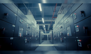
The server in a Data Center hosts and processes the information within milli-seconds onto our digital devices.
As per Reports conducted by Technovia, “The Data Center Asia market is growing at a CAGR of 24 percent, with the Data Center Cooling market alone in India for the financial year 2020-2024 is expected to grow by USD 566.98 Million. According to media agency Zenith, it’s even noted that the media consumption on mobile internet has jumped up from 9.4 minutes daily in 2013 to 54 minutes this year of 2021 in India.
According to data compiled by Visual Capitalist, a single internet minute holds more than 400,000 hours of video streamed on Netflix, 500 hours of video uploaded by users on YouTube and nearly 42 million messages shared via WhatsApp.
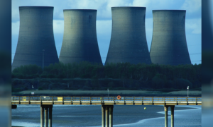
With this, by the year 2030, data centers around the world could be swallowing up to 10 percent to 20 percent of the world’s electricity production compared to 3 percent at present and By 2040 – 5.5 percent of CO2 emissions within a decade with the DC carbon footprint similar to that of the aviation industry .
So, let’s look at what goes into these Data Centres!! (Figure A)
Figure A: 
The Data Centers space shall typically contain components of A. IT equipment’s like servers, PDU …etc and Non IT equipment’s like chillers, Ups, Cooling units. …etc.
Quick overview of the Power usage Effectiveness (PUE) in a Data Center Space with this equipment’s as per ASHRAE norms (Figure B)
Figure B:

What’s interesting to note is that cooling alone takes away the major share close to 30 percent to 40 percent of energy.
The Cooling is by the means of Chillers, Cooling Towers and with “Precision AC” Units the modern termed as “Close Control units” within the Data Center premises these units typically works on a mechanical components equipped with Energy Efficient components to best suit the application by either a refrigerant based Direct Expansion; or a Chiller based Chilled water units; or even a Dual Coil.
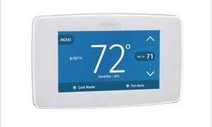
The Precision AC units or Close control units are systems designed to Precisely Control Cooling Temperature in a range of +/- 1°C and Relative Humidity in the range of +/- 5 percent. To meet Critical 24/7 365 days high sensible cooling application such seen in a Data Centers server rooms these cooling units works on a typical vapour compression cycle along with the mechanical components which is a Scroll Compressor, Valves, Fans, Heat Exchanger coils, Heater, Humidifiers in sync with Supply, return and various other sensors which is all integrated and operated with the master intelligent Controller placed on the unit in line with the design concept of “Performance rating of computer and data processing room air conditioners “ as per the AHRI 2017 1360/1361.
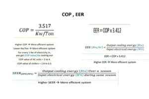
With “ Energy” as the primary focus we also see the above mechanical component enchased to be as Efficient as possible during the Full load and partial load operation with the Scroll compressor upgraded from a Fixed type to a Variable Invertors Compressor, fans from a Axial Type (AC) to a electronically commuted (EC) fans in both indoor and outdoor units, valves from thermostatic to an electronic expansion valves along with other accessories up gradation and keeping in view of the sustainability Global warming the shift from a R407c to R410a now all these up gradation are likely to improve the overall Coefficient of performance ( COP) of the units above 40 percent + overall the traditional mechanical components .
As mentioned earlier these cooling unit are sub divided into 3 more categories based on the site location and availability of water i.e..,
- Refrigerant based Direct Expansion (DX)
- Chiller based Chilled water units (CHW)
- Dual Coil – Combi Cool
Refrigerant-based Direct Expansion (DX):
Working principle is with a Vapour Compression Cycle in sync with all the mechanical components which shall be Refrigerant based circuit; hence the cooling medium shall be “Refrigerants”.
Chiller based Chilled Water Units (CHW):
Working principle is when the cooling units are interconnected with the Chiller and the chilled water from the chiller is the cooling medium, hence the cooling medium shall be “Chiller Chilled water”.
Dual Coil-Combi Cool:
Working principle is with a Vapour Compression Cycle in sync with all the mechanical components which shall be Refrigerant based circuit or when the cooling units are working with two independent Chillers with two different supply and return water temperature however either one chiller can operate at a given time, hence here the cooling medium here shall be either “Refrigerant” + “Chilled water Based” or even “Two Chiller Chilled waters based systems”.
Hence to improve the overall Cooling performance it’s important to select the right mix of Close control units and by choosing the Energy-efficient components alongside what’s also critical is operating at the perfect the “Supply Air Temperature from these Cooling units “ at the Server entry levels and the combination of these would yield the Best in Class Opex Savings .
The below data gives more insight into the “Supply Air Temperature”.
In any Data Center the Server blades are placed horizontally onto the Racks and are designed to take air in at the front (Cold aisle) of the unit and let it out through the back of the unit (Hot Aisle) as indicated in the below Figure – (Figure C).
Figure C:
During the year 1990 and 2000, the data center space was cooled at supply air temperature of close to 12°C like a comfort air-conditioner at our residential homes; which meant the cooling units had to operate at a full load capacity throughout the year which meant higher operational cost. As we entered into the year 2000, the supply air temperature was slightly increased to 15°C, which still meant the same logic of paying higher operation cost. (Figure D).
Figure D: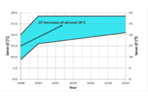
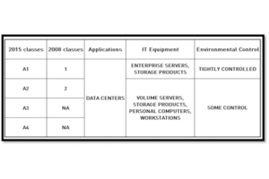
As per ASHRAE 2011/ 2015 (Figure E), the recommended Supply Air temperature at the server inlet level can go as high as 18°C to 27°C, thereby, even maintaining a High Delta ‘T’ between Supply and Return air temperature at the cooling units with the maximum delta ‘T’ of 15°C
(Figure E):

(Figure F) Example: with 2°C supply and max Delta ‘T’ of 15°c the Return air shall go up to 35°C.
(Figure F):
This methodology of operating at higher return air and supply air temperature would have a lower impact of power consumption with higher cooling performance as well from these units and saving close app 35 percent on Power and 45 percent improvement on the Cooling Capacity as compared to a tradition earlier design at a supply air temperature 12°C, Delta 15 deg return and Return Air temperature at 27°C.
Example of 30 TR Module is given below at various supply air temperature and Delta T is mentioned below. (Figure G)
(Figure G): 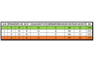
Now the point is if the Server can withstand up to 27oC as per the ASHRAE Norms why not supply Direct outside air at these temperatures instead of running multiple mechanical components which consumes a large extent of power.
Keeping in view of these parameters and Sustainability in mind we see the implementation of “Free Cooling within the Close Control Units. It’s important to note that any Standard Direct Expansion Close Control units shall consume 1.2 ~ 1.4 KW / TR and Free Cool Close Control units shall consume .60 Kw/Tr ~ 0.80 Kw / Tr or even lesser, again depending upon various parameters of capacity, Type of units and ambient from the locations.
Free cooling is cooling the Data Center space with the free ambient air. There mainly two concepts in a free cooling from CCU perspective i.e., Direct Free Cool, Indirect Free Cool
- Direct Free Cool:
- The Close control units are placed near to the wall which is exposed to the outside air and the air is drawn via the Filters into data center space depending within the supply air set point supply of 18°C – 27°C of air temperatures as per ASHRAE norms.
- Air Entering the Data Center should be as per ASHRAE norms of 2011 as below and reference of ASHRAE book of “Particulate and gaseous contamination in Datacom environments” to be used for reference.
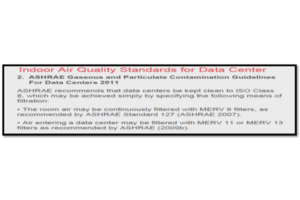
As a case study if the ambient air are above (> 27°C) the units shall operate on the Direct expansion , chilled water or dual modes and if the ambient air is below 27°C up to 18°C the bracket of the Supply Air temperature from the ( ASHRAE Norms ) the direct outside air is drawn via the cooling units into the data center space keeping in note of the filtration as well from ( ASHRAE 2011 Norms ) , in case of the outside ambient air further drops below 18 Deg the damper shall close to re circulate the available air with the DC Space until and unless when the room temperature i.e. the return air temperature further increase which in turn signals the units to reopen the damper to draw the outside cold air to meet the supply air temperature demands all these are controlled and operated via the CCU intelligent controllers and sensors which are placed to monitor the supply air temperature , return air temperature at the rack level or at the given room space , The Air Flow in any CCU is between 500 cfm / tr ~ 600 cfm / Tr or even higher. In a free cool unit the design of the air flow, total static to be considered carefully to meet the site demands.
Fan Curve:
Key Design parameters in Fans:
- Air Velocity – The speed of air in a given direction V = m/s
- Volume flow rate: The amount of air passing a given point in a given unit of time Qv = m3/sec
- Motor Efficiency= power output/ power input • Fan efficiency= air power/fan absorbed power
- Air power= volume flow rate X Total pressure (watts)
- Overall efficiency= Fan efficiency X Motor efficiency
- Static pressure (Ts) Acts equally in all direction which maintains air movement against resistance Total = T internal +T external
Design level static pressure of CCU:
- External Static Pressure: Bottom Flow 50 Pascal, Top Flow 75 Pascal Frontal Flow 30 Pascal
- Components (Internal) App. Static G4 Filter 110 Pascal face velocity 2.5 m/sec
- Coil 3 rows 80 Pascal and 4 rows 110 Pascals Internal components 100 Pascal
Now let’s look at Indirect Free Cool unit- In Direct Free Cool the outside air is restricted to enter the data center, however, leveraging the benefits of a lower ambient temperature. The Indirect Free Cool is further categorised into two methods to choose from –
- In-Direct – Water + Ethylene Glycol based Free Cool
- In-Direct – Air Based Free Cool
- 1 In-Direct – Water + Ethylene Glycol based Free Cool:
The Close Control units shall have separate circuit apart from the Direct Expansion or the Chilled water called the Ethylene Glycol based Water Circuit wherein Water is mixed with Ethylene Glycol at 20 percent ~25 percent to avoid freezing of water at very low ambient temperatures the water + glycol mixture is circulated with the help of a dry cooler or even a Hybrid condenser which operates basis on the outside ambient air temperatures at low ambient air temperature the unit shall operate at
Step 1 – Full Free Cooling mode and further as temperature increase it goes into
Step 2 – Mixed Mode (Partial Free Cool + Partial DX / Chw modes) and finally at higher ambient air temperature it operates at
Step 3- Full DX / Chw Modes By combining all of these steps the users would save close to 20 percent ~ 40 percent or even more depending upon the location, ambient and Type of Data Center and Heat loads within the DC Space. A typical diagram of DX and Free Cool Circuits i.e. Water + Glycol circuit in Blue Color Code with an inbuilt pump system and refrigerant based Circuit in Orange code is shown in
(Figure I). As an additional feature to save on the water circulation method the chilled water from the chiller could also be connected to these units along with the same line of the water + ethylene glycol mixture however either one of the above shall operate at a given time , important to note the set point temperature needs to be set at 15°C to avoid freezing below such temperature and the operational between the chiller or water + glycol mixture circuit can be modulated via automised operated valves, in this case the other circuit can be either DX / Chilled water circuit and shall start operating in mixed and Full DX / Chilled water modes accordingly when the ambient air increases .
(Figure I):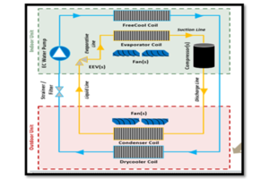
Various Ambient conditions in India wherein the In-Direct – Water + Ethylene Glycol cooling units operates between the Step A Free Cooling ,Step B Mixed Cooling and final Step C DX modes Working Style
(Figure K1) Delhi Ambient, (Figure K2) Kolkata Ambient and (Figure K3) Mumbai Ambient:
(Figure K1)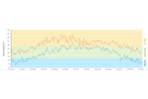
(Figure K2)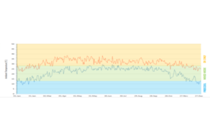
(Figure K3)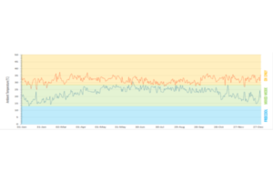
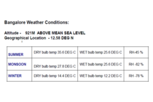
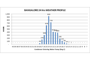
As per ISHRAE the 8760 Hours of weather data for Bangalore is as shown as below, similar reference can be used to evaluate the Savings gained from such Free Cooling units. (Figure L)
(Figure L)
In-Direct – Air Based Free Cool
The Close Control units or also called as Computer Room Handlers ( CRAH ) of higher cooling capacity shall operate with either a Direct Expansion or the Chilled water based circuit along with Adiabatic Cooling pads these pads shall Pre cooling the ambient air before entering to Evaporating coil , in these pads the Water is supplied through a pipe to a distribution pad on top , which ensures an uniform supply of the water to the cooling pad and minuses the risk of dry spots , the water is then evaporated into the dry and warm air that passes the pad , the heat that is needed for the evaporation is taken from the air itself , the air that leaves the pad is therefore cooled and humidified simultaneously , the water that is not evaporated is drained back to the reservoir ( Figure M )
(Figure M)
These CRAH units can either be placed within the Data Center premises or above the Data Center (i.e. Terrace) as per the Configuration shown below; the Blue color code indicates the Supply Cold Air and Red Color code indicates the Return Hot Air. (Figure N)
(Figure N)
The working principle shall be as below:
Condition: Summer Season
Scenario A:
The dry bulb temperature > 35°C and wet bulb of 23°C
Supply Air temperature at 25°C and Return air of 38°C the Delta T shall be 13°C In these conditions, the Fans shall run at full speed, with the compressor or the chiller operational running at full loads and the Adiabatic cooling pads shall be operational.
Scenario B: The Dry bulb temperature < 5°C say 18°C Supply Air temperature at 25°C and Return air of 38°C the Delta T shall be 13°C. In these conditions the fans shall run at partial speed. With the compressor or the chillers in OFF conditions and the adiabatic cooling pads shall be in operational.
Scenario C: The Dry bulb temperature < 18°C Supply Air temperature at 25°C and Return air of 38°C the Delta T shall be 13°C In these conditions the fan shall run at partial speeds, with compressor or the chillers in OFF conditions and the Adiabatic cooling pads shall also be in OFF Conditions Data Analysis from the Figure K and L could be referred to analyses the outside ambient air temperature as per the respective locations to in turn see the running hours of these units to sum up the overall Total Operational Savings derived from such Free Cool units .
The Free Cooling concepts are also available with refrigerant based wherein the refrigerant bypasses the compressors and is directed towards the condenser directly thus saving the operational cost by running the compressor similar free cooling option are also available on “Water Side “via the Chillers on both Water Cooled and Air Cooled Type Chillers which would be integrated to Free Cool Close Control units for a overall improvement of the Cooling COP levels.
Conclusion: “The Free Cooling CCU units COP shall go above > 3.5 which brings down the PUE below 1.2 or below which is an excellent mark for any DC space and with the driving force of Energy Efficiency, Sustainability Free Cool would be the Right Solution to implement at any Data Center Space to Go Green In a Data Center as well to get the Saving during its operational period, so choose the Right Cooling modes with the Free Cool Close Control Units”.
For more info, visit: https://www.flaktgroup.com/in/
Cookie Consent
We use cookies to personalize your experience. By continuing to visit this website you agree to our Terms & Conditions, Privacy Policy and Cookie Policy.