
Most data centres require an uninterrupted cooling to assure adequate working conditions and functionality of the IT equipment. Data centres use thermal storage tanks or chilled water storage tanks as a part of their cooling system for redundancy and emergency cooling.
It is observed that as some data center producers might get tempted by compact looking Ice /PCM based Thermal Energy Storage Systems as well as the false impression about them being a relatively economical option compared to traditional Chilled Water Thermal Storage System. This mythical perception will be broken by the facts and theories stated later in this article, and ultimately Stratified Chilled Water Thermal Storage System will emerge as a tested, proven, reliable and the only reality possible during power outage in data centers for emergency backup cooling. But above all, let us understand why it is critical in data centers to never lose its desired continuous cooling.
What happens in data centers during power outage?
During power failure, the server room air starts to heat up and temperature increases rapidly, and the heat is absorbed by IT equipment. If heat exposure on servers is beyond permissible, there may be unacceptable temperature rise in 5 minutes and IT equipment and data may suffer irreparable loss.
However, subsequently back-up generators turn on which then power the Chillers and this may take 5 minutes to ramp up completely.
The images shown in Fig. 1.0 indicate how devastating intermittent power failures can be for server equipment inside data center if emergency back cooling is not in place. This calls for a solution which is instant and at the same time compatible with the Chilled Water Plant.
Let us therefore begin to speculate which media of TES fits in – Chilled Water or Ice / PCM? To find answers to this question, let us go deep into the hypothesis of Ice TES being used specifically for Data Centre Backup Cooling. The term hypothesis here highlights the fact that Ice TES has never been used for the said application for all the obvious reasons stated in below illustration. What follows, is purely based on assumption; ‘What If?’
What if Ice / PCM thermal storage system is used for CHW backup supply in Data center(s)?
At the event of power outage, following sequence of operation shall take place:
- Return water on the load side continues to recirculate, and if the recirculation happens for 5 minutes, the server room temperature shall rise beyond the acceptable limits.
- The cooling from Ice/PCM storage shall commence in following stages –
Stage One: In a fully charged condition when brine solution flows through TES Tank, Ice / PCM starts to melt and imparts cooling to brine solution gradually. As per ARI-T Guideline for Cool Thermal Storage, this rate of heat transfer /extraction depends on brine flow rate. Higher the brine flow, lower the heat transfer and lesser the rate of cooling imparted, and vice versa. In about 5 minutes or more, the chilled brine of designed temperature reaches the primary side of the PHE.
Stage Two: When first chilled brine enters the PHE, it begins to gradually extract heat from the water side via counter flow mechanism. In another 7 to 10 minutes or more equilibrium is achieved, if all units including, PHE, PHE Pump, Brine Chiller, Brine Pump, Motorised ON/OFF Valves on brine side are properly functional along with right concentration of MEG maintained in Brine. Given the number of variables the combined probability of achieving the intended outcome is hard to promise which is crucial for the mission critical facility.
Stage Three: However, assuming all equipment’s and fluids are in perfect state, the desired temperature on the water side has now been achieved and is good to flow through the Air Handler Coils for generating desired cooling effect.
- Desired flow rate and I/O temperatures of brine solution as well as water on their respective sides of the PHE by means of heat transfer between both fluids has been established. But the time lost in achieving the readiness of chilled water at design supply temperature is nearly 12 to 15 minutes already. All this while the warm return water kept circulating and across circuit and became warmer. As a result, server equipment has already suffered irreparable loss due to all accumulated heat within the racks inside the data center. Any more cooling now is futile.
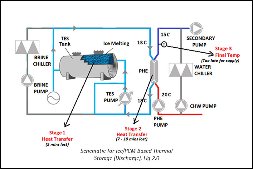
Conclusion: The total time of readiness of supply CHW is 12 to 15 minutes, which should be zero (t=0) for instant discharge. Hence, Ice/PCM Based TES System completely fail to serve the purpose in this application.
Also, Ice/PCM based TES system involves extra equipment (at brine side and PHE), additional fluid category (25 percent MEG Solution), additional temperature ranges (different for charging and cooling at brine side) and dependency on heat transfer through PHE makes the system highly complex and time consuming. Whereas the solution required here must be simple and compatible.
An Ice/PCM based system also requires charging at regular intervals due to periodic loss of cool energy as TES Tanks remains idle for unknown periods when not in use. Charging the Ice Banks is extensively long (even for a very short discharge) and ridiculously high energy consuming (at upto-5°C brine temperature). As a result, high energy and operational cost is incurred.
It is therefore recommended to choose a system that is simple, effective, and efficient that operates with normal Chillers and provides instant discharge (within seconds) to the load, when power failure occurs.
Isn’t chilled water thermal storage the obvious solution…??
Let us now assess chilled water thermal storage system on its candidature of providing Backup Chilled Water for data center cooling. Current industry practice works on the inline schematic (Fig.3), which means that chilled water from chiller passes through CHW TES Tank (s) before reaching the load, thereby keeping the TES ever ready (continuously charged) for emergency discharge.
Fluid (water) used is same as that in chilled water circuit and so are the supply and return temperatures. Hence, system operation and controls simple. Discharge is instant upon power failure.
Also, the charging time is almost same as discharge. Tank pressure drop is negligible, so no extra energy required by pumps.

Conclusion: For reasons stated above, Chilled Water Thermal Storage System proves to be the most efficient, effective, reliable, and simple solution for emergency supply of chilled water for data center cooling.
While CHW TES proves to be the adequate solution for Backup CHW Supply in Data Centers, it is critical to implement the right technique for the intended outcome. Stratified CHW TES is the modern way of storing and discharging chilled water in Air Conditioning applications. It is a calculated, proven, and reliable technology that takes return water mixing into account and uses thermal stratification as a separation method for warm and chilled water due to their density difference.
(This article is authored by – Dinesh Semwal, Managing Director, Ensavior Technologies)
Cookie Consent
We use cookies to personalize your experience. By continuing to visit this website you agree to our Terms & Conditions, Privacy Policy and Cookie Policy.


